Smart Meter: Read Power Consumption and Feed-in with ESP32 and Tasmota
With an ESP32-ETH01, an IR reading head and Tasmota you can read your digital electricity meter yourself: total import and export plus live power, right in your browser and without any cloud service. This guide shows how I set it up on an ISKRA MT681, from the flashing wiring to unlocking the meter with its PIN.
In short
If your meter has an optical port, an ESP32 running Tasmota with SML support and an IR reading head are all you need to track consumption and feed-in continuously.
- You’ll need: an ESP32-ETH01, an IR reading head with TTL output, a USB-to-TTL adapter for flashing and a 5 V power supply.
- Sort this out first: many meters need a PIN for live power readings. In Germany you get it from your metering point operator, so request it early.
- No Raspberry Pi required: Tasmota shows the readings in your browser, so you don’t need a smart home system.
Requirements: will this work with your meter?
You can read digital meters that have an optical port: a small window with an infrared diode on the front, where the reading head attaches magnetically. Most of these meters speak SML, a protocol Tasmota understands. Ottelo, whose firmware and scripts I use here, has tested the Iskra MT174, MT175, MT631 and MT681 and the EMH ED300L, among others. The Tasmota documentation has a longer list with ready-made meter definitions. Old Ferraris meters with a spinning disc don’t have this kind of port.
Many meters only send the totals until you unlock them. Live power readings appear once you enter a four-digit PIN on the meter itself. In Germany the PIN comes from the metering point operator (Messstellenbetreiber), the company that owns the meter. That’s usually your local grid operator, not your electricity supplier, and it’s printed on your bill or on the meter.
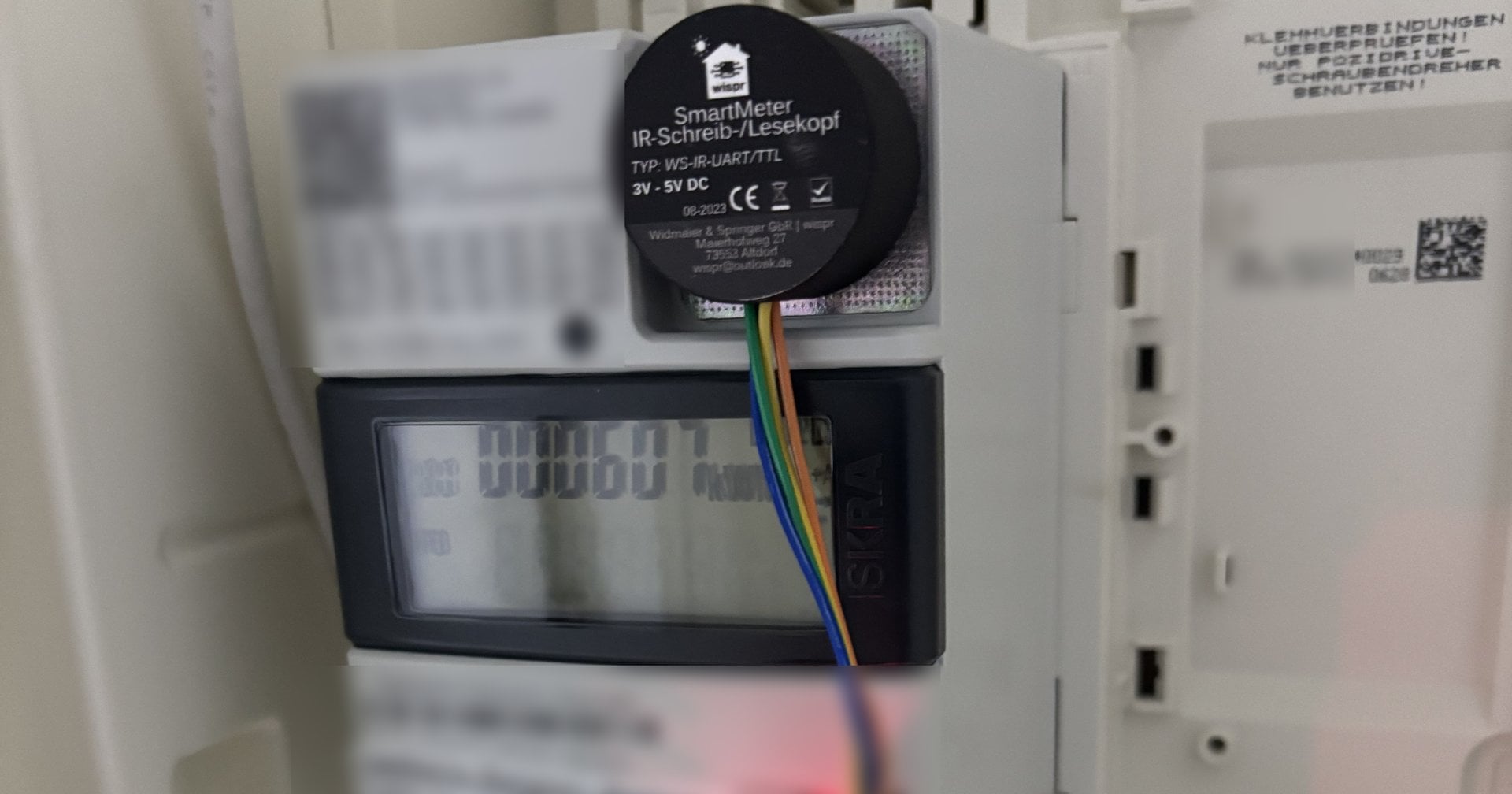
The reading head needs a TTL (UART) output that you wire straight to the ESP32; heads with a USB plug are meant for a Raspberry Pi or PC. You’ll also need power in the meter cabinet for the ESP32 (I use a socket with a USB charger) and a network connection, either Ethernet or Wi-Fi. You don’t open anything on the meter itself: the reading head just sits on the outside of the port, and sealed covers stay closed.
What you’ll need
- ESP32-ETH01 (WT32-ETH01, version 1.4)*
- IR reading head with TTL/UART output* (mine is an IR read/write head from Wispr)
- USB-to-TTL adapter for flashing*
- Jumper wires (DuPont)*
- 5 V power supply* with a DC barrel jack screw terminal adapter*, or an old USB charger with the cable cut open, like I used
As of November 2026: I put this guide together using Ottelo’s Tasmota image v15.0.1 (October 2025). Since v15.1.0 (December 2025) there’s a new workflow where you pick the script and your meter from a drop-down menu instead of entering them by hand. This guide sticks with image v15.0.1. Ottelo covers the new workflow in his guide (in German). Ottelo also now recommends TinyC programs, which come with their own
_tc images, over the Tasmota scripts, which he lists as outdated. This guide sticks with the tested script route on v15.0.1.
Wire up the ESP32 for flashing
The WT32-ETH01 has no USB port, so you flash it through a USB-to-TTL adapter. To put it into flash mode, IO0 stays connected to GND the whole time.

On my DTECH adapter the wires go like this:
- Red (5V) to 5V
- Black (GND) to GND
- White (adapter TXD) to RXD
- Green (adapter RXD) to TXD

Flash Tasmota
For the firmware I use Ottelo’s images. They come with smart meter (SML) support and scripting built in, which the standard Tasmota build lacks. This is the image I tested:
My board ran fine with this generic file. According to Ottelo, though, some WT32-ETH01 boards ship with a single-core chip (ESP32-S1), and those need tasmota32solo1_ottelo.zip from the same release. If your board won’t boot with the generic file, flash the solo1 file the same way.
Unzip the file. You flash it with the Tasmota Web Installer in Chrome or Edge, since other browsers can’t access the serial port. Step by step:
- Wire everything up as shown above, with IO0 still connected to GND.
- Plug the adapter into your PC. The ESP32 draws its power from the adapter’s 5 V line.
- Briefly bridge EN to GND, then remove the bridge. This reset boots the ESP32 into flash mode.
- In the web installer, pick
tasmota32_ottelo.factory.binvia “Upload factory.bin”. - Click “Connect” and choose the adapter’s COM port in the browser dialog.
- Tick “Erase Device”, start the installation and wait until the installer reports that it’s done.
- Unplug USB and remove the bridge between IO0 and GND.
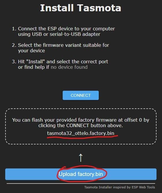
Ottelo himself currently can’t get the web installer to work and uses Espressif’s Flash Download Tool instead. If the web installer gets stuck for you too, switch to that tool; Ottelo’s guide (in German) walks through the steps.
Then plug the adapter back in. Without the bridge, Tasmota boots normally, and the adapter keeps the board powered until you install it in the meter cabinet.
Set up Tasmota: Wi-Fi, module and Ethernet
On first boot the ESP32 opens its own Wi-Fi network called tasmota-xyz. Connect to it from your phone or PC and the setup page usually pops up on its own.

Enter your regular Wi-Fi details. Write down the address shown after saving, because that’s where you’ll find Tasmota in your browser from now on. Mine was http://192.168.178.193.

Go to “Configuration”, then “Module”, choose “WT32-Eth01” as the module type and save.

Now plug in the network cable, open “Tools” → “Console” and enter these two commands one after the other:
EthAddress 1
EthClockMode 0
EthAddress 1 sets the address of the Ethernet chip. According to Ottelo, EthClockMode 0 is needed because the web interface gets very sluggish otherwise when the board is only connected by cable.
If you want a static IP address, you can set one too. The address and gateway (usually your router) have to match your network; the subnet mask is usually 255.255.255.0 and the DNS server is usually your router again:
EthIpAddress 192.168.178.196
EthGateway 192.168.178.1
EthSubnetmask 255.255.255.0
EthDNSServer 192.168.178.1
EthIpAddress 0.0.0.0 switches back to automatic addressing (DHCP). To see which address the board got over Ethernet, run EthIpAddress on its own: it’s the one in brackets, 192.168.178.196 in my case.

Open the new address in your browser once. If it loads, you can turn Wi-Fi off with Wifi 0. If you’re sticking with Wi-Fi, skip the Ethernet commands and use the Wi-Fi address in the script later on.
Connect and mount the reading head
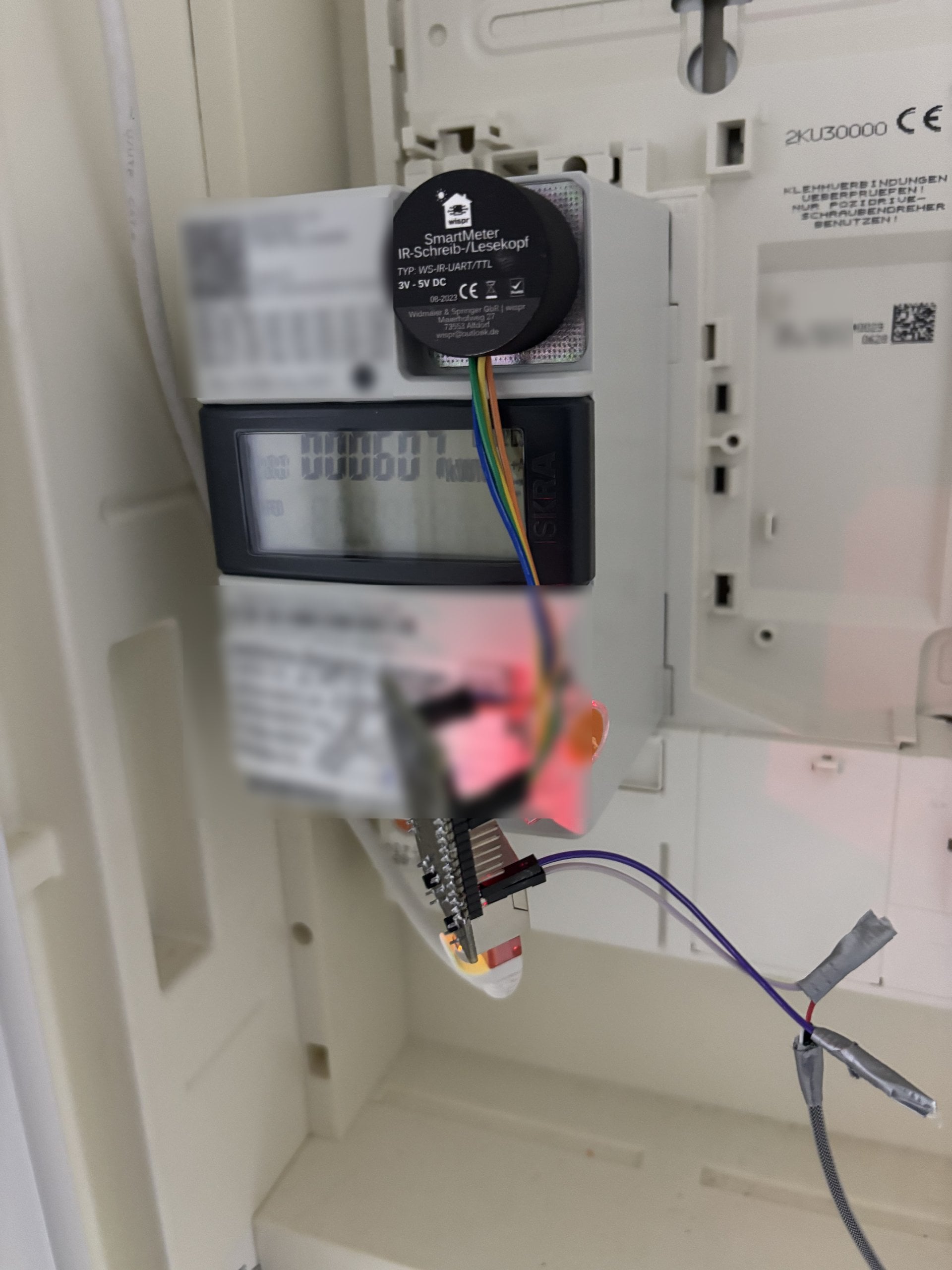
Unplug the USB-to-TTL adapter first. The reading head goes on the same TXD and RXD pins, and from now on the power supply feeds 5V and GND. Connect the reading head with jumper wires: VCC to 3V3, GND to GND and the two data lines to TXD and RXD. The line the head sends its data on goes to RXD (GPIO 3), because that’s where Tasmota listens. Your head’s manual tells you which one that is. If no readings show up later, swap the two lines.

An old USB charger works fine as a power supply: cut the cable open, solder a jumper wire to the red (5 V) and black (GND) cores and insulate the joints. Here’s how it all sits in the meter cabinet:

Set up the script and your meter
A script from Ottelo does the number crunching. For image v15.0.1, use the scripts in the ESP8266 folder of his repository. Ottelo no longer updates them, but says they run on the ESP32 as well. The scripts in the main folder need image v15.1.0 or later. Which one you pick depends on your meter: a bidirectional meter counts import and export separately, an import-only meter just counts what you draw from the grid. With balcony solar or a PV system you’ll usually have a bidirectional meter, and its display shows 2.8.0 (export) alongside 1.8.0 (import). Your options include:
1_SML_Script_Chart: no solar panels or balcony solar, so no feed-in2_SML_Script_Chart_PV: with feed-in, for bidirectional meters2_SML_Script_Chart_PV_2: like _PV, plus a high-resolution power chart (one value every 5 seconds). This is the one I use for my balcony solar.3_SML_Script_Chart_PV_1-Richtungszaehler: like _PV, but for import-only meters, with feed-in calculated
First remove the comments at the top of the script, as Ottelo recommends. Near the top there’s an IP address: replace it with your ESP32’s Ethernet address, IP=192.168.178.196 in my case. Then open “Tools” → “Edit Script” in Tasmota, tick “Script enable” and paste the script.

At the end of the script you’ll find the >M 1 section with the meter definition. Replace only that part with the definition for your meter and leave the other sections, such as >D and >B, as they are. The order of the three value lines below the header line +1,… matters: power, import, export. The script’s daily totals and charts rely on it. For the ISKRA MT681, Ottelo’s own meter definition looks like this:
>M 1
+1,3,s,0,9600,MT681
1,77070100100700ff@1,Leistung,W,Power,16
1,77070100010800ff@1000,Verbrauch,kWh,ImportActive,3
1,77070100020800ff@1000,Einspeisung,kWh,ExportActive,3
#
The 3 in the header line is the GPIO the reading head’s data line is connected to (RXD on the WT32-ETH01). Power is signed: positive when you draw from the grid, negative when you feed in. The labels (Leistung = power, Verbrauch = import, Einspeisung = export) are what Tasmota shows on its home page, so feel free to rename them. If power isn’t the first value line, the script reports it as daily consumption. The definition comes from Ottelo’s maintained meter list. Definitions for other meters are in Ottelo’s meters folder or in the Tasmota docs.
After saving, the Tasmota home page shows your import and export totals; live power only appears once you’ve unlocked the meter (next section). When the totals and power look right, initialise the script once by entering script>=#init in the console. This resets the daily, monthly and yearly totals to zero so the charts start fresh.
Unlock the meter for live power readings
Out of the box, my ISKRA meter only sends the totals. To get live power as well, you enter the PIN with a flashlight (your phone’s works fine) by shining it on the light sensor on the front of the meter. Your meter’s manual shows where it is; if the reading head is in the way, take it off for now. On the ISKRA it works like this:
- Shine the light on it for about 5 seconds until the PIN prompt appears.
- Enter the four-digit PIN: each short flash increases the current digit by one. After 3 seconds without light, it moves on to the next digit.
- Once the PIN is in, keep flashing briefly until the display shows “Inf Off”.
- Now hold the light on it for 5 seconds until “Inf On” appears. From then on, the meter sends live power too.
Other meters use different menu names; your meter’s manual describes the steps.
No readings? Try this
- Nothing at all: Rotate the reading head by 180 degrees and make sure it’s centred on the port. If that doesn’t help, swap the two data lines.
- Totals but no live power: The meter isn’t unlocked yet (“Inf Off”).
- Daily totals look wrong: Check the order of the three value lines under
>M 1, then initialise the script again.
Ottelo collects more fixes in the FAQ of his guide.
Conclusion
With just a few inexpensive parts you can watch your meter’s consumption and feed-in live in your browser, with no cloud and no app from your grid operator. It pays off most if you have balcony solar or a PV system, since you see straight away how much you’re exporting and when you’re pulling power from the grid. The bulk of the effort is the one-off flashing and getting the meter definition right. After that, the ESP32 just sits quietly in the meter cabinet. A natural next step is sending the readings to Home Assistant via MQTT; our guide to MQTT on the Raspberry Pi covers the basics.
Frequently asked questions about reading your smart meter
Digital meters with an optical port that send data using the SML protocol. Ottelo has tested the Iskra MT174, MT175, MT631 and MT681 and the EMH ED300L, among others, and the Tasmota documentation lists many more meters with ready-made definitions. Old Ferraris meters with a spinning disc don’t have this kind of port.
In Germany, from the metering point operator (Messstellenbetreiber), the company that owns the meter. That’s usually your local grid operator rather than your electricity supplier. Without the PIN, many meters only send the import and export totals, not live power.
For the ESP32 you need a head with TTL (UART) output, which you wire straight to 3V3, GND, RXD and TXD. Heads with a USB plug are meant for a Raspberry Pi or PC and won’t connect to the WT32-ETH01.
Yes. According to the Tasmota documentation, Tasmota sends its readings via MQTT and Home Assistant’s Tasmota integration discovers the devices automatically. Ottelo covers the setup in dedicated chapters of his guide.
From image v15.1.0 onwards you pick the script and your meter from a drop-down menu instead of entering them by hand. This guide covers the v15.0.1 route. Ottelo labels some of his newest releases as test versions and recommends going back one release if you want a stable build. For new setups, Ottelo now recommends TinyC programs over Tasmota scripts, which is also a different route from the one in this guide.