
What exactly sits on the Arduino UNO Q – and what is it for? This interactive board overview shows you every connector and every important chip right on the photo of our test board: click one of the numbered dots and you get the explanation – including the logic-level pitfalls. To get the board up and running, follow our guide Arduino UNO Q Setup; all other articles are collected in the Arduino category.
The Arduino UNO Q combines two processors: the Qualcomm QRB2210 (front) runs Debian Linux, the STM32U585 (back) runs your Arduino sketches. The classic UNO headers work with 3.3 V logic (not 5 V like the UNO R3!), the Qwiic connector does too, and the JCTL debug console even uses only 1.8 V. Power comes via USB-C (5 V/3 A), the 5 V pin or VIN (7–24 V).
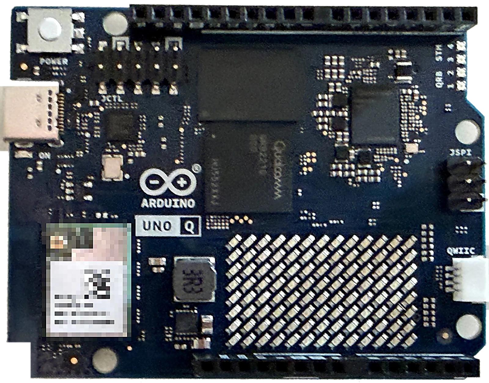
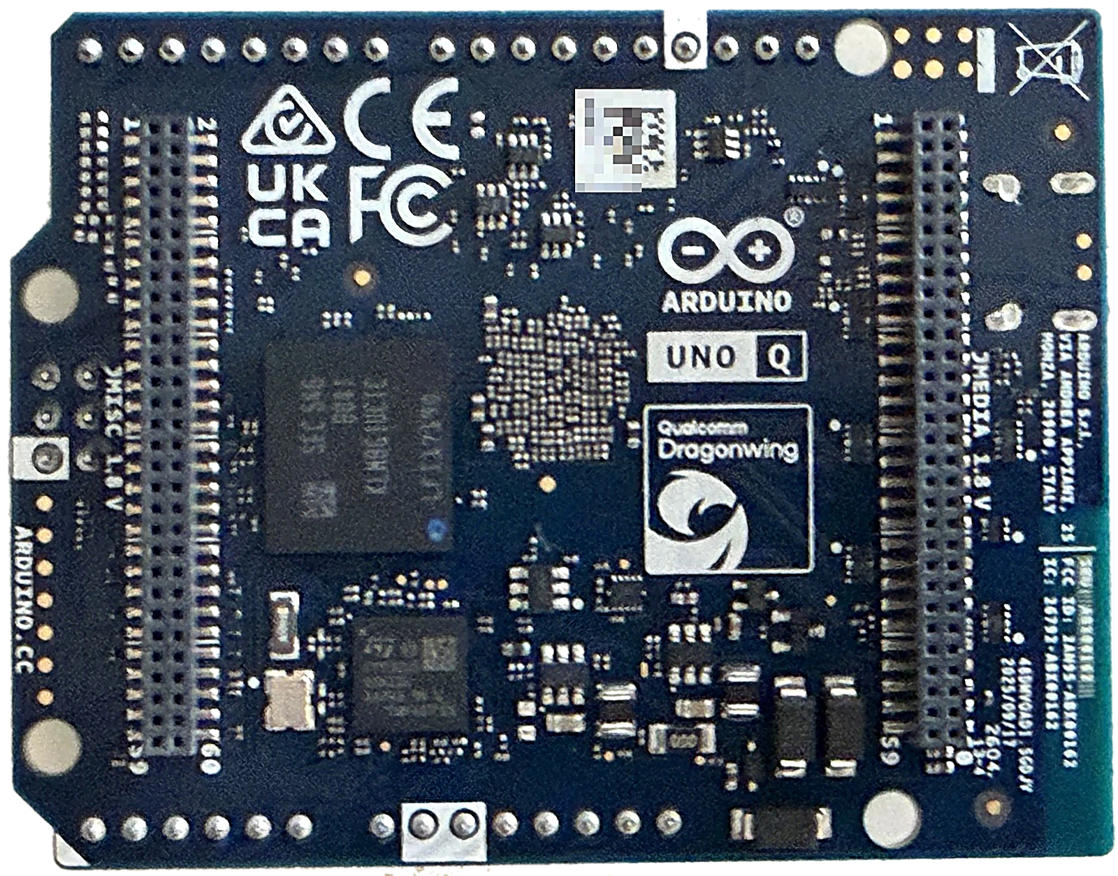
👆 Click a numbered dot to find out what sits there.
1 · USB-C port (JUSB1)
The board’s only socket: USB 3.1 for data, power (5 V/3 A – Power Delivery deliberately negotiates no higher profile) and video. The small ANX7625 chip next to it converts the Qualcomm processor’s display signal to DisplayPort Alt Mode – up to Full HD, 720p optimal. For desktop use you need a USB-C dock with Power Delivery.
2 · Power button
An on/off switch – unthinkable on a classic UNO, necessary here because a full Debian Linux wants to shut down cleanly instead of simply losing power.
3 · JCTL: debug console
Serial console for bootloader and system messages before SSH or ADB are available. ⚠️ Operates at 1.8 V logic – never connect an ordinary 3.3 V or 5 V USB-UART adapter.
4 · Qualcomm QRB2210 + RAM
The Linux brain: Qualcomm Dragonwing QRB2210 with four Cortex-A53 cores @ 2.0 GHz and an Adreno 702 GPU (845 MHz), with the LPDDR4X RAM (2 or 4 GB) right next to it. This is where the Debian system, App Lab apps and containers run.
5 · Power management (PMIC)
The supply centre around Qualcomm’s PM4145 PMIC: generates the many internal voltage rails for processor, RAM and radio from the 5 V input.
6 · Wi-Fi & Bluetooth module
WCBN3536A radio module (Qualcomm WCN3980) with Wi-Fi 5 (2.4/5 GHz) and Bluetooth 5.1, antenna on board. The white sticker carries the board’s MAC address (redacted here).
7 · Voltage regulator
The buck converter with the chunky 3R3 inductor efficiently converts the input voltage for the board. Power comes via USB-C (5 V/3 A), the 5 V pin or VIN at 7–24 V.
8 · 8×13 LED matrix
104 blue LEDs driven by the STM32: shows the animated Arduino logo at boot and can be used freely in your sketches and App Lab projects – for tickers, status displays or little games.
9 · Digital header (JDIGITAL)
The classic UNO header: D0–D13 plus SCL/SDA/AREF/GND, electrically connected to the STM32. ⚠️ 3.3 V logic instead of the old UNO R3’s 5 V – pure 5 V shields need a level shifter. Six pins support PWM, D0/D1 are the hardware UART (Serial1).
10 · Analog & power header (JANALOG)
A0–A5 are connected to a 14-bit ADC (much finer than the UNO R3’s 10 bits); A0 and A1 can even output voltages as a DAC. Plus the supply pins: 5 V, 3V3, VIN, GND and reset.
11 · SPI header (JSPI)
Separate SPI connector (3.3 V) on the STM32 – for displays, radio modules and other fast peripherals.
12 · Qwiic connector
I²C connector in the Qwiic standard (Wire1, 3.3 V only): connect sensors and Arduino’s Modulino modules with a simple cable – no soldering, no breadboard.
13 · Status & user LEDs
Two RGB LEDs: one freely usable user LED and one system LED (red = panic/error, green = Wi-Fi, blue = Bluetooth). Both can also be controlled from the Linux side via /sys/class/leds.
1 · eMMC storage
The soldered-on mass storage (16 or 32 GB): home of Debian, App Lab and your data. There is no SD card like on the Raspberry Pi – so the variant you buy decides your storage.
2 · STM32U585 microcontroller
The real-time brain: Arm Cortex-M33 at up to 160 MHz, 2 MB flash and 786 kB SRAM. Runs your Arduino sketches on Zephyr OS and manages the LED matrix as well as all 3.3 V headers on the front.
3 · Carrier connector JMISC
60-pin connector with mixed levels (1.8/3.3 V): GPIO, SDIO, I²C, parallel camera and the audio endpoints (microphone, headphones, line-out). Used via matching carrier boards that plug in from below.
4 · Carrier connector JMEDIA
60-pin connector (1.8 V) for the fast signals: MIPI-CSI cameras and MIPI-DSI displays. The display signal is shared with the USB-C port – only one of the two can output at a time.
All components at a glance
For everyone who prefers reading over clicking – the front side from left to right:
Front
- USB-C (JUSB1): USB 3.1 for data, power (5 V/3 A) and DisplayPort Alt Mode (via ANX7625, up to Full HD, 720p optimal).
- Power button: boots and shuts down the Debian system cleanly.
- JCTL: debug console for boot messages – careful, 1.8 V logic!
- Qualcomm QRB2210 + LPDDR4X RAM: four Cortex-A53 @ 2 GHz, Adreno 702 GPU, 2/4 GB RAM – the Linux side.
- Power management (PM4145 PMIC): generates the internal voltage rails.
- Wi-Fi/BT module WCBN3536A: Wi-Fi 5 dual-band + Bluetooth 5.1 with onboard antenna.
- Voltage regulator: buck converter for the 5 V supply (USB-C, 5 V pin or VIN 7–24 V).
- 8×13 LED matrix: 104 blue LEDs, freely programmable, driven by the STM32.
- JDIGITAL: D0–D13 + SCL/SDA/AREF – 3.3 V logic, 6× PWM, UART on D0/D1.
- JANALOG: A0–A5 with 14-bit ADC (A0/A1 also DAC) plus 5 V/3V3/VIN/GND/reset.
- JSPI: SPI header (3.3 V) on the STM32.
- Qwiic: I²C plug connector (Wire1), 3.3 V only – for sensors and Modulinos.
- Status LEDs: user RGB LED + system LED (panic/Wi-Fi/Bluetooth).
Back
- eMMC storage: 16/32 GB soldered on – operating system and data, no SD card.
- STM32U585: Cortex-M33 @ 160 MHz, 2 MB flash – runs the Arduino sketches.
- JMISC: 60-pin carrier connector (1.8/3.3 V) for GPIO, SDIO, audio and parallel camera.
- JMEDIA: 60-pin carrier connector (1.8 V) for MIPI camera and display.
The most important rule: mind the logic levels
The UNO Q looks like a classic UNO – electrically it is not. The rule of thumb for all connectors:
| Connector | Logic level | What it means for you |
|---|---|---|
| JDIGITAL, JANALOG, JSPI, Qwiic | 3.3 V | Modern sensors: connect directly. Old 5 V shields: only with a level shifter. |
| JCTL (debug) | 1.8 V | Only connect a 1.8 V-capable USB-UART adapter – 3.3 V can damage the board. |
| JMEDIA (carrier) | 1.8 V | For MIPI cameras/displays via carrier boards – nothing to wire up directly. |
| JMISC (carrier) | mixed 1.8/3.3 V | Check the pin assignment in the datasheet before connecting anything. |
All details down to the individual pin assignment are in the official Arduino datasheet and pinout PDF. And if your UNO Q is still sitting in its box: start with our step-by-step guide Arduino UNO Q Setup. Happy tinkering!