Raspberry Pi: Enable SPI and I2C – Complete Guide
The Raspberry Pi has a sophisticated data bus system for communicating with other devices and modules. Whether sensors, displays, real-time clocks or other microcontrollers – almost all of them use I2C, SPI or UART. In this article we’ll show you how to correctly enable and test these interfaces on Raspberry Pi OS.

What is I2C?
I2C is a serial protocol for a two-wire interface. It connects devices like EEPROMs, A/D and D/A converters, sensors, displays and other ICs over just two lines: SDA (data) and SCL (clock). Originally developed by Philips, it is now used by virtually all IC manufacturers.

What is SPI?
The Serial Peripheral Interface (SPI) bus is a synchronous data bus system developed by Motorola. It works on a master-slave principle and is used for short distances – typically in embedded systems, sensors and SD cards.
SPI has four signal lines:
- SCLK: Serial Clock (master output)
- MOSI: Master Output, Slave Input
- MISO: Master Input, Slave Output
- SS/CE: Slave Select / Chip Enable (active low)

What is UART?
The Universal Asynchronous Receiver Transmitter (UART) is a serial interface used for sending and receiving data. The key feature: no separate clock signal is needed – both sides simply need to use the same baud rate. UART is often used for serial consoles, GPS modules or communication with microcontrollers.

GPIO pin assignment for I2C, SPI and UART
| Interface | Signal | GPIO pin (board) |
|---|---|---|
| I2C | SDA (I2C1) | Pin 3 |
| I2C | SCL (I2C1) | Pin 5 |
| UART | TX | Pin 8 |
| UART | RX | Pin 10 |
| SPI | MOSI | Pin 19 |
| SPI | MISO | Pin 21 |
| SPI | SCLK | Pin 23 |
| SPI | CE0 | Pin 24 |
| SPI | CE1 | Pin 26 |
Popular modules for I2C and SPI
If you’re just getting started with I2C or SPI, you’ll often wonder: which modules are worth using? Here are some classics that are well-documented and work reliably with the Raspberry Pi:
- BME280 – measures temperature, humidity and air pressure via I2C or SPI. Ideal for weather station projects: View BME280 sensor module*
- SSD1306 – small 0.96″ OLED display via I2C, perfect for displaying readings directly on the Pi: View SSD1306 OLED display*
- MCP3008 – 8-channel ADC via SPI, for reading analog sensors (e.g. potentiometers, LDRs) on the digital Pi: View MCP3008 ADC*
- DS3231 RTC – real-time clock via I2C, keeps the time even without internet: View DS3231 RTC module*
- Jumper cables – for wiring between GPIO pins and modules: View jumper cable set*
Enable I2C and SPI via raspi-config (recommended)
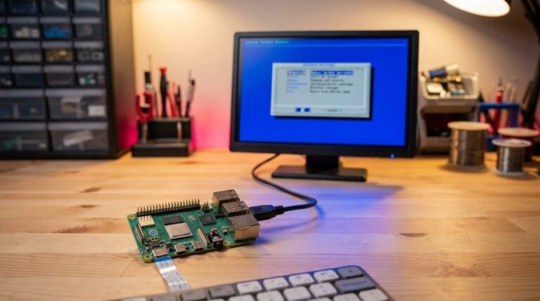
The easiest method is the raspi-config configuration tool. Open a terminal and enter:
sudo raspi-config
Navigate to 3 Interface Options. There you’ll find:
- I4 SPI – enable SPI
- I5 I2C – enable I2C
Select the desired interface, confirm with Yes and reboot the Pi:
sudo reboot
Enable I2C and SPI via config.txt (headless / Raspberry Pi OS)
If you’re not using a desktop or working headless, you can enable the interfaces directly in the config file. With Raspberry Pi OS, this is at /boot/firmware/config.txt (no longer at /boot/config.txt):
sudo nano /boot/firmware/config.txt
Add the following lines at the end of the file:
# Enable I2C
dtparam=i2c_arm=on

# Enable SPI
dtparam=spi=on
Save with Ctrl+X, Y, Enter. I2C needs one more step: the Device Tree doesn’t load the i2c-dev module, which creates the device file /dev/i2c-1. raspi-config adds it for you, but on the config.txt route you add it yourself:
echo i2c-dev | sudo tee -a /etc/modules
Then reboot:
sudo reboot
Note: You no longer need the old module names i2c-bcm2708 and spi-bcm2708 in /etc/modules, or to unblock anything in /etc/modprobe.d/raspi-blacklist.conf. The Device Tree loads the I2C and SPI drivers from config.txt. The only exception is the i2c-dev module you just added.
Test I2C with i2cdetect
After rebooting, install the I2C tools and check whether a connected device is detected:
sudo apt install i2c-tools -y
sudo i2cdetect -y 1
The output shows a matrix with the I2C addresses of all found devices. An RTC like the DS1307 appears at address 68, for example:
     0  1  2  3  4  5  6  7  8  9  a  b  c  d  e  f
00:          -- -- -- -- -- -- -- -- -- -- -- -- --
...
60: -- -- -- -- -- -- -- -- 68 -- -- -- -- -- -- --
70: -- -- -- -- -- -- -- --
If you see no output, check your wiring and whether I2C is correctly enabled.
Test SPI
After enabling SPI, the device files should be present:
ls /dev/spi*
You should see /dev/spidev0.0 and /dev/spidev0.1. If so, SPI is correctly active.
Python example with smbus2 (I2C)
The old i2c-bcm2708 library from earlier tutorials is no longer used. In Python today you use smbus2. Under Raspberry Pi OS you either install the system package or use a virtual Python environment:
Option 1 – system package (simplest):
sudo apt install python3-smbus2 -y
Option 2 – smbus2 via pip in a virtual environment:
python3 -m venv ~/venv-i2c
source ~/venv-i2c/bin/activate
pip install smbus2
A simple example that reads a value from I2C address 0x68 (e.g. an RTC):
#!/usr/bin/env python3

import smbus2

# I2C bus 1 (default on Raspberry Pi)
bus = smbus2.SMBus(1)

# Address of the device (e.g. DS1307 RTC at 0x68)
DEVICE_ADDRESS = 0x68

# Read seconds register (register 0)
seconds = bus.read_byte_data(DEVICE_ADDRESS, 0)
print(f"Seconds register (BCD): 0x{seconds:02X}")

bus.close()
Tip: For more complex I2C projects, it’s worth looking at adafruit-circuitpython-busdevice, which supports many sensors out of the box.
Enable UART
Enabling UART differs slightly from I2C and SPI, because the Raspberry Pi uses the serial console on the UART by default. How to correctly set up UART is covered in a separate article: Enable UART on Raspberry Pi.
Frequently asked questions about I2C, SPI and UART
I2C uses only two wires (SDA and SCL) and lets several devices share one bus, each with its own address. That makes it a good fit for sensors and small displays. SPI uses four wires (MOSI, MISO, SCLK, CS) and is much faster: I2C usually runs at 100 or 400 kHz, SPI at several MHz. In return, every SPI device needs its own chip select pin. Use I2C when you want to wire up lots of devices easily, SPI when throughput matters.
After enabling I2C in raspi-config, install the tools with sudo apt install i2c-tools and run i2cdetect -y 1. The scan shows every device it finds as a hex address in a grid. Common ones: 0x27 or 0x3F for LCDs with a PCF8574 backpack, 0x76 or 0x77 for the BME280 and 0x3C for SSD1306 OLED displays.
Open raspi-config and go to 3 Interface Options → I6 Serial Port. Answer No when it asks about a login shell over serial and Yes when it asks about the serial port hardware. After a reboot, the UART on pins 8 and 10 is available as /dev/serial0. On a Pi 5 or Pi 500, use /dev/ttyAMA0 instead, because serial0 points to the separate debug connector there.
Yes, they use different GPIO pins and can all run at once. There’s one quirk on the Pi 3, Pi 4, Zero W and Zero 2 W: Bluetooth uses the full UART there, so the GPIO header gets the simpler mini UART (ttyS0). That’s fine for GPS modules and similar devices. You only need to turn off Bluetooth if you need the full UART. The Pi 5 has a dedicated UART for Bluetooth, so the conflict doesn’t exist there.
All devices share the same two wires, so the real limit is the address space: each device needs a unique address. For typical projects with a handful of sensors and a display, that’s never an issue. If two devices have the same fixed address, an I2C multiplexer such as the TCA9548A lets you switch between them.
The usual suspects: I2C isn’t enabled in raspi-config, SDA and SCL are swapped, the module has no power, or there’s a loose contact on the breadboard. Check the wiring against the pinout (SDA = pin 3, SCL = pin 5) and reboot the Pi once after enabling the bus. If i2cdetect complains that /dev/i2c-1 is missing, the i2c-dev module isn’t loaded (check with lsmod | grep i2c_dev); add it to /etc/modules as described in the config.txt section.
The most common causes: SPI isn’t enabled (raspi-config, or dtparam=spi=on in /boot/firmware/config.txt), the wrong chip select pin (CE0 = GPIO 8, CE1 = GPIO 7), or the wrong SPI mode in Python (spidev defaults to mode 0, some devices need mode 1, 2 or 3). Also check the wiring: MOSI on the Pi goes to MOSI (or DIN) on the device, not to MISO. ls /dev/spi* shows whether the SPI device files exist.
Conclusion
I2C and SPI are the Raspberry Pi’s most important serial interfaces, and raspi-config switches both on in a minute. I2C is ideal for hooking up lots of sensors over just two wires, SPI for fast data transfer to ADCs, displays and SD cards. In Python, smbus2 is the go-to library for I2C and spidev for SPI. All three interfaces can run at the same time.