
Low-Cost Wi-Fi Temperature Sensor with NodeMCU ESP8266 – DIY Guide
By chance I came across the NodeMCU IoT developer board – a compact microcontroller with built-in Wi-Fi and a USB interface for programming. That combination dramatically speeds up development, so I decided to take a closer look and build a real IoT project with it right away. Using a Lolin NodeMCU V3 ESP8266 board I built a battery-powered Wi-Fi temperature and humidity sensor with a DHT22 sensor.
Why the NodeMCU V3 ESP8266?
A while ago I built temperature sensors based on RFM69CW 433 MHz modules and ATtiny84A microcontrollers – but the assembly and programming effort is considerable and sets a high barrier for beginners. When one of my 433 MHz sensors fell victim to water damage I would have had to order new PCBs, so I chose the straightforward Wi-Fi alternative instead. NodeMCU boards are developer/prototype boards that aren’t ideal for final production use – but at this price point that doesn’t matter much. The main drawback is the relatively high current consumption of these “bloated” dev boards.
Where are the measurements sent?
As the receiver for my existing 433 MHz setup I already had a Raspberry Pi running a 433 MHz receiver and a script (emonhub) forwarding data to my EmonCMS installation. Since the NodeMCU can send data directly over Wi-Fi, I skip the middleman and transmit the readings in JSON format straight to EmonCMS. If you don’t want to run your own server you can create a free account at emoncms.org, or modify the sketch to use any other cloud service.
Hardware
Parts list:
- NodeMCU V3 ESP8266 ESP-12E* – ~€6
- 2×AA battery holder* – ~€1
- DHT22 sensor + 4.7 kΩ resistor* – ~€5
- Female/female jumper cables (×4)* – ~€0.50
- 2×AA alkaline batteries* – ~€0.50
- For programming (one-time): Micro-USB cable* – ~€3
At roughly €13 (excluding shipping) the cost per sensor is very low – at that price point you get practically nothing comparable on 433 MHz, let alone over Wi-Fi.
Batteries
There are several ways to power a NodeMCU project from batteries. I chose two AA alkaline batteries – not optimal, but it avoids the need for an LDO voltage regulator (as required with 3.7 V LiPo cells) or a special charger (as with 14500 LiFePO4 cells). Note that some NodeMCU boards may not function reliably at 3 V (2×1.5 V AA). A safer and still inexpensive option is 3×1.5 V alkaline cells with an HT7333 LDO regulator, but I wanted to skip the extra soldering.
=> Update: with 2×AA batteries, DeepSleep enabled and a 5-minute measurement interval, my NodeMCU lasted 11 days. With further hardware modifications battery life on two AA cells can certainly be extended further.
Software Setup – Arduino IDE
I program the board with Arduino IDE 2 on a Windows PC (screenshots: version 2.3.10). The menus and dialogs look the same on macOS and Linux.
Once it’s installed, setting up the IDE takes three steps: the ESP8266 board package, the board selection and the DHT library.
To let the IDE program (flash) the ESP8266, open File → Preferences (Ctrl + comma) and paste this URL into Additional boards manager URLs:
https://arduino.esp8266.com/stable/package_esp8266com_index.json
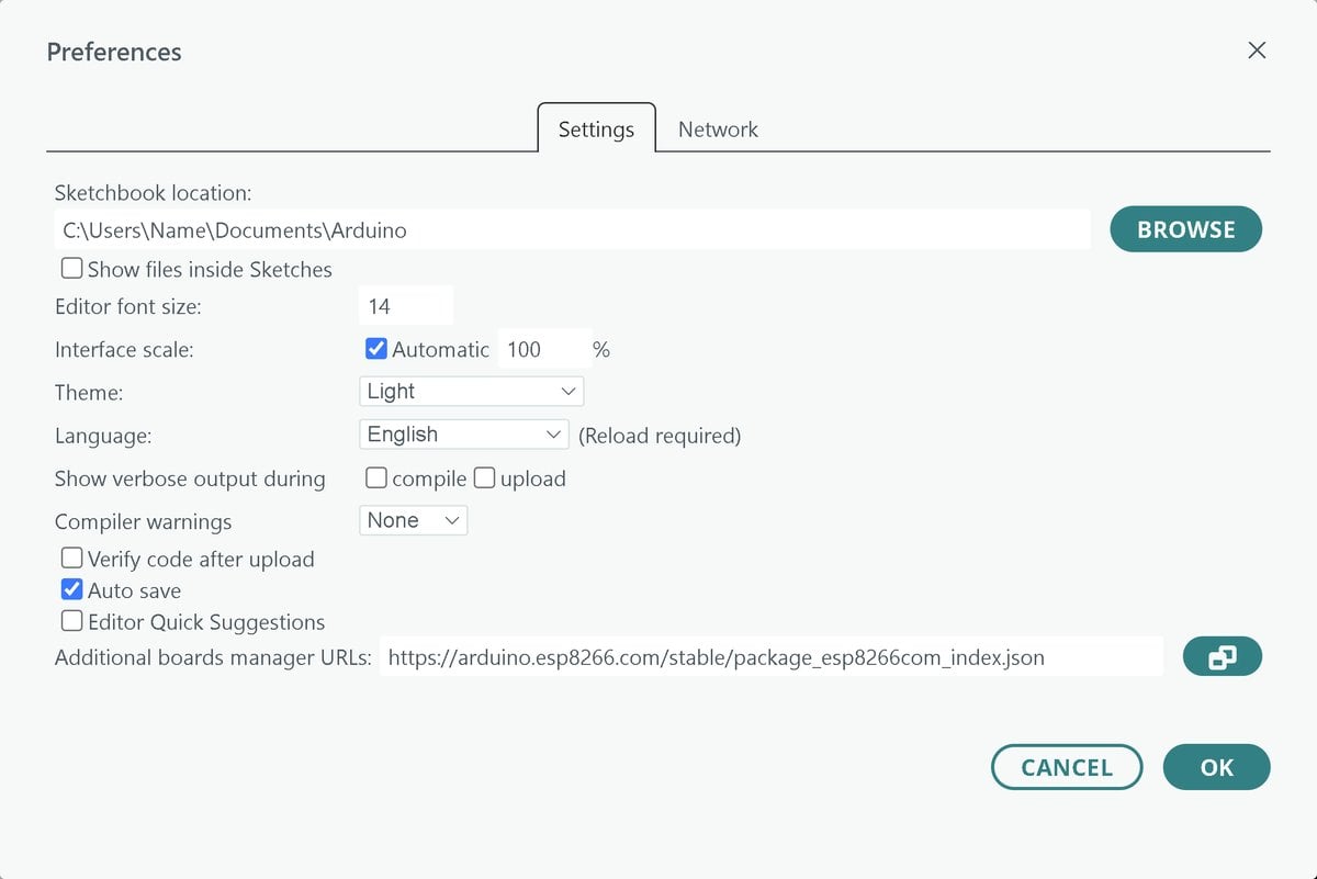
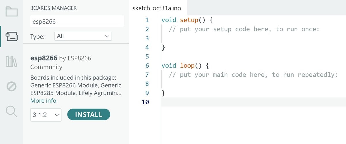
Click OK and the IDE downloads the package index. Then open the Boards Manager from the sidebar on the left (second icon, or Tools → Board → Boards Manager), search for esp8266 and click Install on “esp8266 by ESP8266 Community”. The download takes a few minutes.
Next, pick the board: click Select Board in the toolbar, then Select other board and port…. Search for “nodemcu” and choose NodeMCU 1.0 (ESP-12E Module). On the right, select the port your NodeMCU is connected to, usually COM3; if several show up, try them one by one.
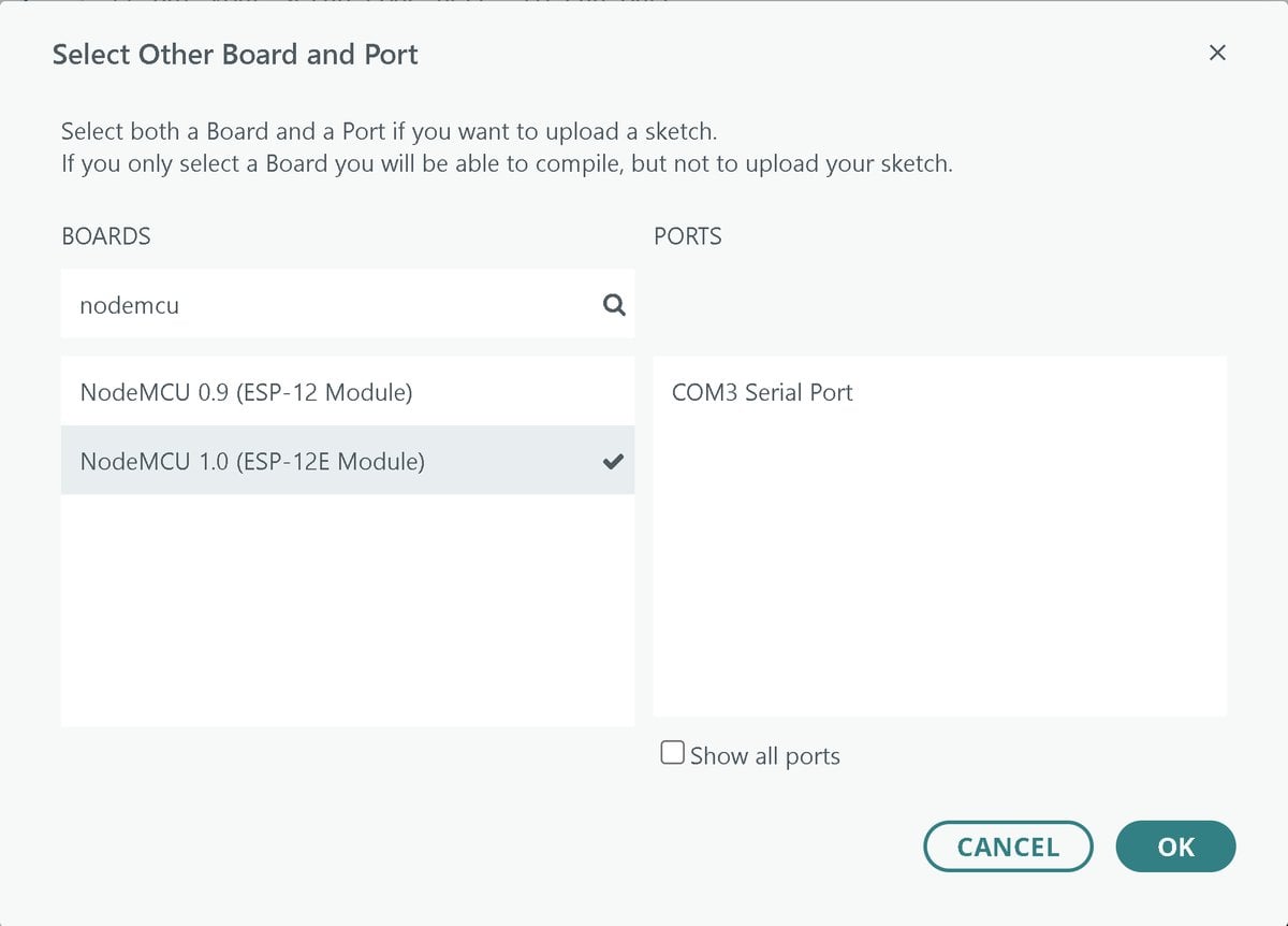
You can leave the other options under Tools as they are: the defaults (80 MHz CPU, 4 MB flash, 115200 upload speed) are fine.
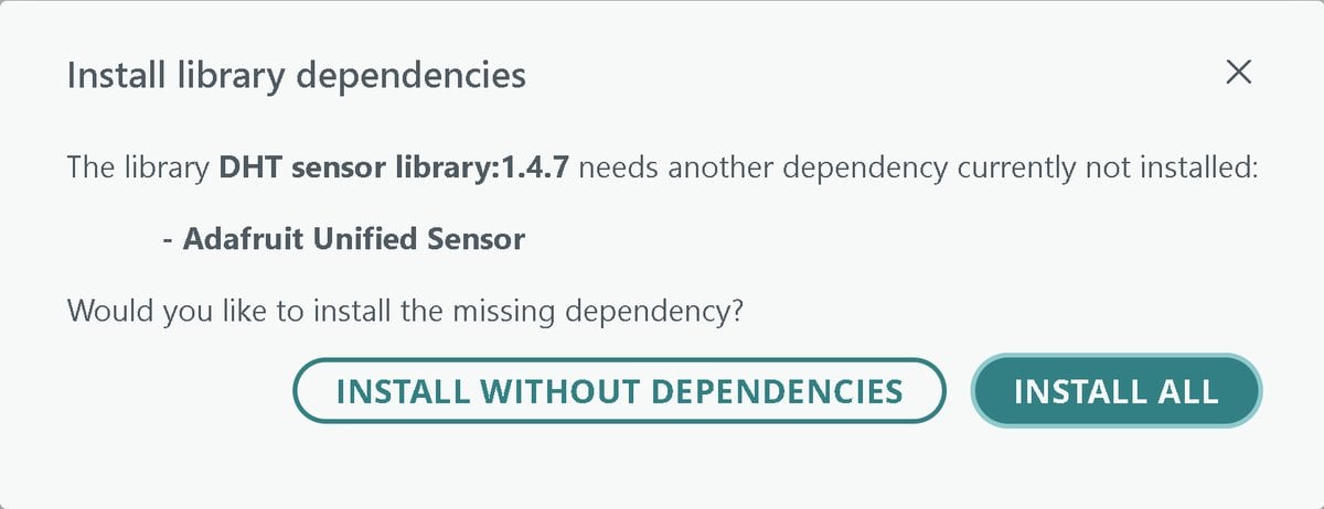
The DHT22 also needs a library. Open the Library Manager from the sidebar (third icon, or Sketch → Include Library → Manage Libraries), search for “DHT sensor library” and install the one by Adafruit. The IDE will then ask about the missing “Adafruit Unified Sensor” library – click Install all.
Wiring the DHT22
The wiring is straightforward – you only need four female jumper cables, the DHT22 sensor and a 4.7 kΩ resistor.
- One jumper cable between D0 and RST to enable DeepSleep – blue
- DHT22 Pin 1 (VCC) to 3.3 V – red
- DHT22 Pin 2 (Data) to D1 – yellow
- DHT22 Pin 3 – leave unconnected
- DHT22 Pin 4 (GND) to GND – black
- 4.7 kΩ resistor between DHT22 Pin 1 and Pin 2

Without a breadboard – just jumper cables – my setup looks like this. Since the node will later sit in an enclosure the loose wiring isn’t a problem.

Important: Connect the battery only after everything has been tested and programmed.
Programming – DHT22 Sketch for NodeMCU with DeepSleep
The following sketch sends sensor data to EmonCMS. To minimise execution time and thus power consumption it uses a fixed IP address and omits all Serial debug output. The sketch runs every 5 minutes; in between, the NodeMCU enters deep sleep. If it can’t connect to Wi-Fi within ten seconds, it goes back to sleep anyway so the battery doesn’t drain.
You need to adjust the Wi-Fi credentials, IP address and EmonCMS details for your environment. Make sure each node has a unique node ID and that you use the correct Write API Key.
The version with Serial debug output for testing is available on GitHub.
/**
   Send DHT22 Sensor Data to EmonCMS and go to deep sleep - Without Serial Debug Output
   Philipp Schweizer - http://raspberry.tips
   08.10.2017 - Initial Version
*/

// Including the Libraries for WiFi Connection, HTTP Send and DHT22 Sensor
#include <ESP8266WiFi.h>
#include <WiFiClient.h>
#include "DHT.h"

// Replace with your network details
const char* ssid = "fritzbox";
const char* password = "xxxxx";
//Provide IP Address, Gateway, Subnet and DNS matching your network
IPAddress ip(192, 168, 178, 211); // I use fixed IP-Address
IPAddress gateway(192, 168, 178, 1); // set gateway to match your network
IPAddress subnet(255, 255, 255, 0); // set subnet mask to match your network
IPAddress dns(192, 168, 178, 1); //DNS Server = Router IP

// DHT Sensor settings
#define DHTTYPE DHT22
const int DHTPin = 5;
DHT dht(DHTPin, DHTTYPE);

//emoncms settings, change node ID for every node
const char* host = "emoncms.org";
const char* nodeId   = "31";
const char* privateKey = "xxx";
const int httpPort = 80;

//Seconds to deep sleep 300 = 5 min
const int sleepTimeInSec = 300;

//Variables to store values
float h = 0;
float t = 0;
int vcc;
ADC_MODE(ADC_VCC);

// ==============================================
// only runs once on boot then go deep sleep again
// ==============================================
void setup() {

  //Start sensor
  dht.begin();

  // Sensor readings may also be up to 2 seconds 'old', so we read twice
  h = dht.readHumidity();
  t = dht.readTemperature();
  delay(3000);
  h = dht.readHumidity();
  t = dht.readTemperature();
  vcc = ESP.getVcc();

  //Connect WiFi
  //Fix  https://github.com/esp8266/Arduino/issues/2186
  WiFi.config(ip, gateway, subnet, dns);
  delay(100);
  WiFi.persistent(false);
  WiFi.mode(WIFI_OFF);
  WiFi.mode(WIFI_STA);
  WiFi.begin(ssid, password);

  // Give up after 10 seconds so a missing WiFi does not drain the battery
  unsigned long wifiStart = millis();
  while (WiFi.status() != WL_CONNECTED) {
    if (millis() - wifiStart > 10000) {
      ESP.deepSleep(sleepTimeInSec * 1000000);
    }
    delay(500);
  }

  //Send data to emoncms
  sendData();

  //go to deep sleep
  ESP.deepSleep(sleepTimeInSec * 1000000);
}

// ==============================================
// Send Data to emoncms
// ==============================================
void sendData() {

  WiFiClient emonHTTPClient;

  //Connect by http
  const int httpPort = 80;
  if (!emonHTTPClient.connect(host, httpPort)) {
    return;
  }

  //Build the JSON for emoncms to send data
  String json = "{temperature:";
  json += t;
  json += ",humidity:";
  json += h;
  json += ",vcc:";
  json += vcc;
  json += "}";

  //Build emoncms URL for sending data to
  String url = "/input/post.json?node=";
  url += nodeId;
  url += "&apikey=";
  url += privateKey;
  url += "&json=";
  url += json;

  // Send the HTTP Request to the emoncms server
  emonHTTPClient.print(String("GET ") + url + " HTTP/1.1\r\n" +
                  "Host: " + host + "\r\n" +
                  "Connection: close\r\n\r\n");
  delay(500);

  emonHTTPClient.stop();
}

void loop(void) {
}
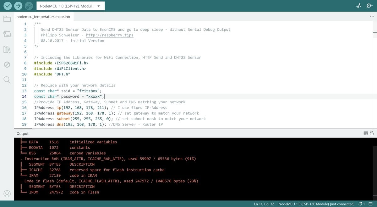
To upload, connect the NodeMCU to your computer via USB and click Upload (the arrow icon in the top left) in the Arduino IDE. The IDE compiles the sketch and flashes it to the board. There’s no need to press the FLASH button: the NodeMCU’s USB-to-serial chip uses its DTR and RTS lines to put the board into flash mode automatically.
If the upload still fails with “Failed to connect to ESP8266”, do it manually: unplug the board, hold down the FLASH button right next to the Micro-USB port, plug the USB cable back in and start the upload again.
If everything worked, a new node (node 31 by default) should appear in your EmonCMS instance. You can assign it to a feed and visualise it in a dashboard. EmonCMS is quite intuitive, so I’ll skip further setup details here. As an alternative to the cloud version you can install EmonCMS on your Raspberry Pi on your home network – the easiest way is the EmonPi image.

Running NodeMCU on Battery
The NodeMCU V3 board is specified for 3.0–3.6 V input.
Since I want to run the temperature sensor independently of a mains supply, I use a 2×AA battery holder. To keep things flexible I crimped two female jumper sockets onto the battery holder wires – alternatively you can solder the holder directly to the pins or add female headers and protect the joints with heat-shrink tubing.
I use the 3.3 V and GND pins near the reset switch; any 3 V / GND pins on the board will work.


Important: To bypass the onboard voltage regulator (which wastes power), I connect the battery directly to the 3 V and GND pins. If you use different batteries you may need to go through VIN or the 5 V pin, depending on your battery voltage. Note that ESP.getVcc() does not return a reliable value in this setup – I haven’t found a way to read battery status without a multimeter. Battery voltage drops quite quickly and I suspect two AA alkaline cells fall below the minimum 3 V within a few days.
Conclusion
Running on AA or AAA batteries, the NodeMCU Wi-Fi temperature sensor is currently not a replacement for my 433 MHz sensors – the current consumption is simply too high without more invasive modifications (e.g. desoldering the LDO and the USB-UART chip). Building from individual components (ESP-12 Wi-Fi module + ESP8266 SoC directly) is too much work for me. That said, if you need a quick solution, a stationary installation, or simply want a fun project to build and program, the NodeMCU approach is hard to beat for its simplicity.