
ESPHome + Raspberry Pi: Build Your Own Smart Home Sensors
ESPHome turns an ESP32 board into a custom sensor for Home Assistant, and your Raspberry Pi builds the firmware for it. In this guide you’ll build three sensors on one board: a BME280 that measures temperature, humidity and air pressure, a window contact, and a motion sensor. Where there’s no outlet nearby, you can build the temperature sensor on a battery-powered board instead. Everything stays on your own network. You’ll need a Raspberry Pi running Home Assistant OS, but no microcontroller experience.
In short
You describe your sensor in a few lines of YAML, and ESPHome turns that into firmware for an ESP32. All the Pi needs is the ESPHome Device Builder app in Home Assistant. The sensors can go anywhere in the house with Wi-Fi coverage.
- What to buy: an ESP32 board with a WROOM-32 module and USB-C for all three sensors (climate, window and motion), a USB data cable and a USB power supply.
- How it works: install the app, create a device and flash it over USB once. After that, each new sensor is a YAML block you add and install over Wi-Fi.
- Running on battery: the Seeed XIAO ESP32-C3 with a LiPo battery and deep sleep. Ideally, add the sensor and deep sleep before the first flash: once it sleeps, it only takes updates during its short wake windows. To last for weeks, it should wake up no more than once every 10 minutes.
What is ESPHome, and what does the Raspberry Pi do?
A microcontroller like the ESP32 is a tiny computer on a single chip that runs exactly one program, its firmware. It has built-in Wi-Fi and pins (GPIOs) you connect sensors to. Unlike a Raspberry Pi, it has no operating system.
With ESPHome, you don’t program that firmware yourself. You write a short YAML file that says which board you’re using and which sensor is connected to which pin, and ESPHome builds the firmware from it. Since version 2026.6 you can also pick the board and components from a catalog, but under the hood it’s still the same YAML file. ESPHome mainly targets the ESP32 and ESP8266, plus a few other chips.
- The ESP32 runs the firmware. It reads the sensor and sends the values over Wi-Fi.
- The Raspberry Pi runs the ESPHome Device Builder as an app in Home Assistant. This is where you create devices, edit their YAML files and compile them into firmware.
- Home Assistant adds each device through the ESPHome integration.
After the first install, new firmware reaches the board OTA (over the air, meaning over Wi-Fi), so you only need the USB cable once.
Unlike a Pi 4 or 5, the Raspberry Pi Pico 2 W is itself a microcontroller and can run ESPHome firmware. Our guide Raspberry Pi Pico 2 W with ESPHome shows how.
Which ESP32 board should you buy?
| Option | Best for | Connector | Power | What to know |
|---|---|---|---|---|
| ESP32 board with WROOM-32 | all three projects, with a power outlet nearby | USB-C | USB power supply | choose “ESP32 DevKit V1” in the Device Builder |
| Seeed XIAO ESP32-C3 | a temperature sensor with no outlet nearby | USB-C | LiPo battery, charges over USB-C | battery must be soldered on; readings only every few minutes, updates only while it’s awake; can’t power the motion sensor (no 5 V on battery) |
For most projects, pick a classic ESP32 development board with the ESP32-WROOM-32 module and a USB-C port, like this one*. All pins and configs in this guide match it, and its 5 V pin powers the motion sensor. Avoid two variants. WROVER boards reserve GPIO16 internally, and this guide needs that pin for the motion sensor. The WROOM-32U/-32UE has no built-in antenna, so it needs an external one.
The Seeed XIAO ESP32-C3 has a LiPo charging circuit on board and draws very little in deep sleep (details in the battery section). A Wemos D1 Mini (ESP8266) runs ESPHome too, but the GPIO numbers in this guide don’t apply to it. On the D1 Mini, for example, I2C uses GPIO4 (D2) for SDA and GPIO5 (D1) for SCL.
If there’s already a network cable where the sensor will go, consider an ESP32 board with Ethernet and PoE, such as the Olimex ESP32-POE from the Device Builder’s board catalog. A single cable carries both power and data, but the Ethernet port takes up several GPIOs, so the sensors need different pins than in this guide.
If you’d rather not wire or solder anything, get the ESPHome Starter Kit from Apollo Automation: a ready-made kit with an ESP32-C6 and sensor modules, with its own guide on esphome.io.
For the basic differences between the ESP32, Arduino and Raspberry Pi, see our guide Raspberry Pi vs. Arduino vs. ESP32. If you buy an ESP32-C6, it can also work as a Zigbee router.
What you need
- a Raspberry Pi 4 or 5 running the 64-bit version of Home Assistant OS (setup: Install Home Assistant on Raspberry Pi; hardware: Raspberry Pi 5 vs. N100 mini PC)
- ESP32 board with WROOM-32 and USB-C*
- a USB-A to USB-C data cable* for a Pi or PC with USB-A ports, or a USB-C data cable* for a computer with USB-C
- breadboard and jumper wires*, ideally two breadboards
- BME280 module* for project 1. Make sure the listing says “BME280”. The BMP280 looks almost identical but doesn’t measure humidity.
- MC-38 wired reed switch* for project 2
- HC-SR501 motion sensor* for project 3
- a USB power supply (1 A or more) to run the board 24/7, such as the official Raspberry Pi power supply with USB-C cable*
- Building the battery sensor? Its parts are listed in the battery section.
A breadboard lets you connect parts without soldering. An ESP32 board is so wide that a single breadboard leaves little or no room next to its pins. Put two breadboards side by side and seat the board across both. One breadboard is enough if you connect the sensors straight to the board’s pins with jumper wires.
For connections on the breadboard, use jumper wires with a pin on both ends (male-to-male). Wherever a wire plugs straight onto a header pin on the board or a sensor, that end needs to be female (male-to-female or female-to-female). A kit with all three types covers everything. Some BME280 modules ship with loose header pins that you have to solder on first. If you’d rather not solder, look for a module with the header already attached.
Install the ESPHome app in Home Assistant
- In Home Assistant, go to Settings → Apps → Install app.
- Search for “ESPHome”. The “ESPHome” section lists three entries: open ESPHome Device Builder, not the “(beta)” or “(dev)” versions.
- Click Install.
- On the Info tab, turn on “Show in sidebar” and click Start. “ESPHome Builder” now shows up in the sidebar.
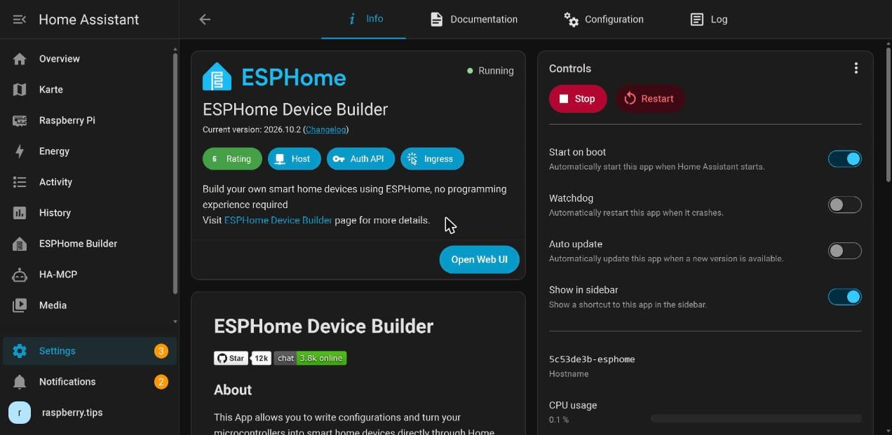
If your Pi still runs a 32-bit Home Assistant OS, the app shows up as “Not available” and can’t be installed.
The first build on the Pi takes several minutes. If a build takes more than five minutes, the Device Builder suggests handing builds to a faster machine (Set up a build server). This is optional. To use it, install the ESPHome desktop app (Windows, macOS or Linux) on your PC and pair it in the Device Builder. The Pi then hands its builds to the PC whenever the app is running.
Create your first device in the Device Builder
- Open “ESPHome Builder” in the sidebar. The first time, a short setup dialog appears. Click Continue on the welcome screen, leave “New to ESPHome” selected under “Choose your experience” and click Continue again. On the last screen, click Start guided tour for a walkthrough, or skip it with Maybe later.
- Click Create device in the bottom-right corner.
- When asked “How would you like to create your project?”, choose Create new project.
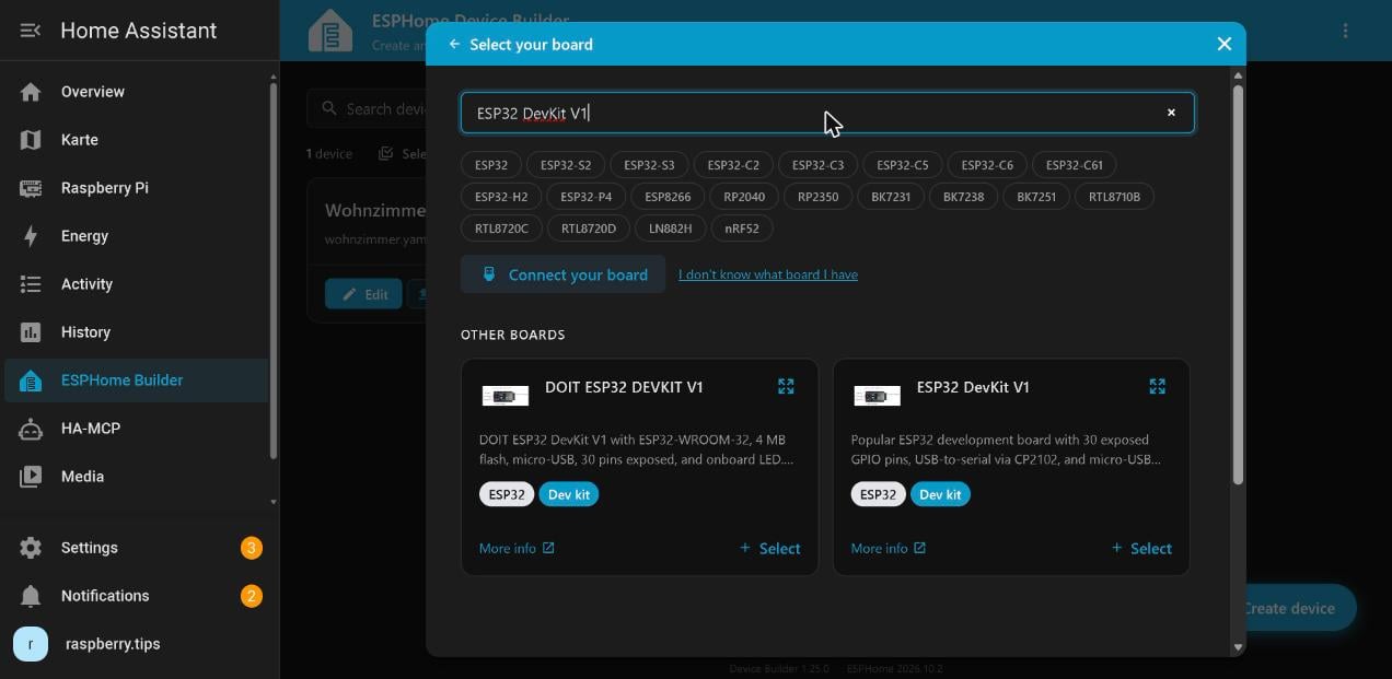
- Under Select your board, type “ESP32 DevKit V1” into the search box. You’ll get two matches, “DOIT ESP32 DEVKIT V1” and “ESP32 DevKit V1”. Click Select on “ESP32 DevKit V1”. Its description mentions micro-USB, but it works for WROOM-32 boards with USB-C too, because the chip and the GPIO numbers are the same. Optionally, if you plug the board in now, Connect your board (below the chip-family buttons) detects the chip. If you opened Home Assistant over HTTPS in Chrome, Edge or Firefox, plug it into your computer; otherwise, plug it into the Pi. You still pick the exact board from the list. For the battery sensor, search for “XIAO ESP32C3” instead and pick “Seeed XIAO ESP32C3”, not the “Seeed Studio XIAO ESP32C3” entry without a description.
- Under Name your device, enter a name in the “Device name” field, for example “Living room” (or “Bedroom” for the battery sensor), and click Next. Home Assistant will show the device under this name.
- Under Wi-Fi Configuration, enter your Wi-Fi name and password. The Device Builder saves them and reuses them for every new device, so you won’t see this step again.
- Click Finish setup.
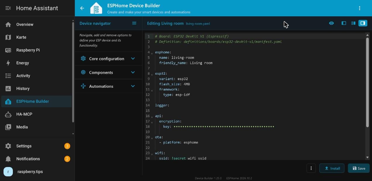
The Device Builder now opens the editor (“Editing Living room”). On the right is the YAML file it generated; on the left, the device navigator, where you can also add components with a few clicks. To get back here later, click Edit on the device’s card on the Device Builder home page. The file looks like this (with the key and password blanked out):
# Board: ESP32 DevKit V1 (Espressif)
# Definition: definitions/boards/esp32-devkit-v1/manifest.yaml

esphome:
  name: living-room
  friendly_name: Living room

esp32:
  variant: esp32
  flash_size: 4MB
  framework:
    type: esp-idf

logger:

api:
  encryption:
    key: "…"

ota:
  - platform: esphome

wifi:
  ssid: !secret wifi_ssid
  password: !secret wifi_password
  ap:
    ssid: "Living room Fallback Hotspot"
    password: "…"

captive_portal:
The lines starting with # are comments. Here’s what each section does:
esphome:holds the internal name and, infriendly_name, the name you see in Home Assistant.esp32:describes the chip, flash size and framework (ESP-IDF).logger:turns on logging. The Logs icon on the device card shows what the board reports in real time, such as the I2C addresses it found or Wi-Fi errors. It looks like a box with lines of text, sits in the row of buttons at the bottom of the card and shows “Logs” when you hover over it.api:is the connection to Home Assistant. Thekeyencrypts it, and every device gets its own.ota:allows updates over Wi-Fi.wifi:uses!secretto pull your Wi-Fi name and password from thesecrets.yamlfile where the Device Builder stored them.ap:andcaptive_portal:are the fallback hotspot. If the board can’t find your Wi-Fi, it opens its own network called “Living room Fallback Hotspot”. Connect to it with your phone and a page opens where you can enter the Wi-Fi details again. The hotspot password is in your file underap:.
There’s one line you need to add yourself: encryption: under ota:. ESPHome encrypts Wi-Fi updates with the API key anyway, but without this line the board also accepts unencrypted ones. With it, the board refuses them. The block should now look like this:
ota:
  - platform: esphome
    encryption:
The empty
encryption:entry uses the same key asapi:, so you don’t need a separate OTA password. The ESPHome documentation has recommended this since version 2026.9.
Click Save in the bottom-right corner.
Building the battery sensor with the XIAO ESP32-C3? Don’t flash it yet. Skip ahead to the battery section instead. The sensor and the deep sleep block are best in its config from the first flash on: once it sleeps, it only accepts updates over Wi-Fi during the few seconds it’s awake, so flashing it without
deep_sleep:first just means flashing it a second time.
Flash the board over USB and add it to Home Assistant
Until the board has been flashed for the first time, its card in the Device Builder shows “Offline”.
- Connect the ESP32 board to a free USB port on the Pi with the data cable.
- Click Install in the bottom-right corner of the editor. On the device card, it’s the icon with the upward arrow.
- When asked “How do you want to install the firmware?”, choose Plug into your Home Assistant server, then pick the board’s port under “Select a serial port”. If something else is plugged into the Pi, such as a Zigbee stick, and you’re not sure which port is which, unplug the board, plug it back in and pick the port marked “New”. The third option, On the network, is for every install after this one.
- Wait while the Device Builder compiles the firmware and flashes it.
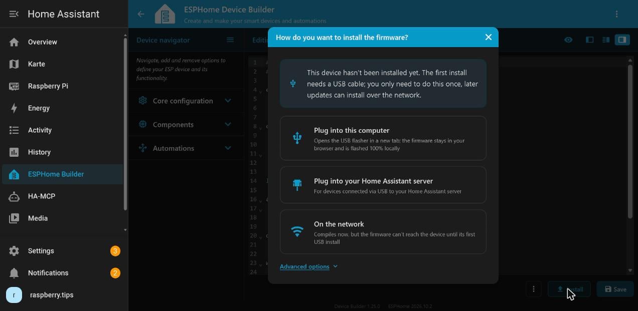
If the Pi isn’t close by, use your PC instead: plug the board into the PC, click Install and choose Plug into this computer. This works in Chrome, Edge and Firefox 151 or later, because the browser talks to the USB port directly. If you access Home Assistant over plain HTTP (no HTTPS), the Device Builder offers a button that opens a separate tab where you connect the board and install the firmware. If your browser blocks the tab, allow pop-ups for the site. The firmware goes straight from your browser to the board and is never uploaded to a server.
If no port shows up, it’s almost always one of these three things:
- The cable only charges and doesn’t carry data. Use a data cable.
- Your PC is missing the driver for the board’s USB-to-serial chip. The chip’s name is printed on the board or given in the product listing, usually a CP210x or CH34x. Download the driver from the chip maker’s website.
- The board doesn’t enter flash mode. Hold the BOOT button while plugging in the cable, then let go.
Once the firmware is running and the board is on your Wi-Fi, its card switches to “Online”. Home Assistant discovers it automatically. Go to Settings → Devices & services, look under “Discovered” and click Add. If nothing shows up there, add the device by hand as described in Troubleshooting.
From now on, you install every change over Wi-Fi: click Save, then Install → On the network. The USB cable is then only needed for power. For the projects, the board can stay plugged into the Pi or run from a USB power supply. Unplug it before you wire up a sensor.
Project 1: temperature, humidity and pressure with the BME280
The BME280* is the first of the three sensors on the “Living room” board. It talks over I2C, a bus with two data lines (SDA and SCL) that several sensors can share. Most modules already have the required pull-up resistors on board. The older DHT22 only measures temperature and humidity and needs a pin of its own. If you already have a DHT22*, use ESPHome’s dht platform; the ESPHome DHT docs cover the wiring and config.
Wiring
BME280 → ESP32
VCC    → 3V3 (3.3 V)
GND    → GND
SCL    → GPIO22
SDA    → GPIO21

Only on 6-pin modules:
CSB    → 3V3 (I2C mode)
SDO    → GND (address 0x76)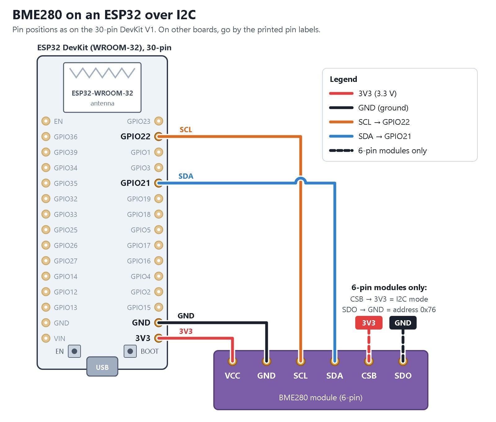
Pin positions vary between boards, for example between 30-pin and 38-pin versions, so go by the labels printed next to the pins. GPIO21 is often labeled just “21”, “D21” or “G21”.
According to Bosch’s datasheet, the sensor chip itself is rated for 3.6 V at most. Some modules have a voltage regulator and are sold as “5V”, but they almost always run on 3.3 V too, so connect VCC to 3V3 either way.
Configuration
Add this block to the end of the file (indent with spaces, not tabs) and install it over Wi-Fi:
i2c:
  sda: GPIO21
  scl: GPIO22
  scan: true

sensor:
  - platform: bme280_i2c
    temperature:
      name: "Temperature"
      oversampling: 16x
    pressure:
      name: "Pressure"
    humidity:
      name: "Humidity"
    address: 0x76
    update_interval: 60s
scan: true writes the I2C addresses found on the bus to the log at startup. After the update, open the log with the Logs icon on the device card. If the scan reports 0x77, use that address instead of 0x76. Older guides still use platform: bme280, but current ESPHome versions use bme280_i2c (or bme280_spi for SPI).
Because friendly_name is set, short names like “Temperature” are enough: Home Assistant groups the readings under the “Living room” device. To see them, go to Settings → Devices & services, click ESPHome and then the “Living room” device to see the current values. No humidity reading? Then your module is a BMP280, not a BME280.
Project 2: window contact with a reed switch
The second sensor on the “Living room” board is an MC-38 reed switch*. It comes in two parts, a magnet and a switch with a cable attached, and changes state when the magnet comes close. You don’t need an external resistor, because the ESP32 has a built-in pull-up.
Wiring and configuration
Reed switch, wire 1 → GPIO4
Reed switch, wire 2 → GND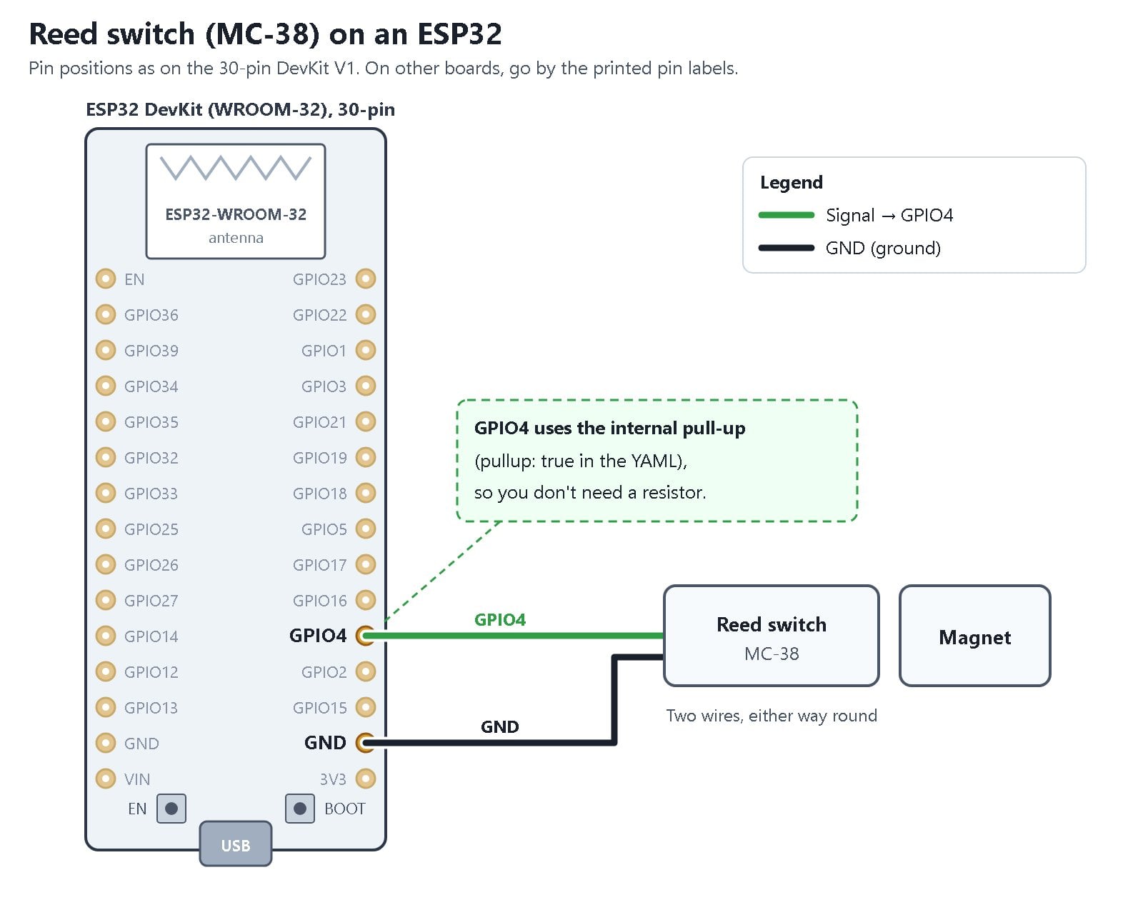
Push the reed switch’s two wire ends into two free rows of the breadboard, then connect those rows to GPIO4 and GND with jumper wires. If the thin stranded wires won’t go in, twist the ends tightly first. It doesn’t matter which wire goes to GPIO4 and which to GND.
Add this block to the end of the file and install it over Wi-Fi:
binary_sensor:
  - platform: gpio
    pin:
      number: GPIO4
      mode:
        input: true
        pullup: true
    name: "Window"
    device_class: window
    filters:
      - delayed_on: 10ms
      - delayed_off: 10ms
pullup: true turns on the built-in resistor. The two filters debounce the contact, so a brief flicker as the window closes doesn’t register as several openings.
After the update, check that the state is reported correctly. Reed switches come in two types: one closes when the magnet is near, the other opens. Hold the magnet against the switch. If Home Assistant then shows “Open”, add inverted: true under pin::
    pin:
      number: GPIO4
      mode:
        input: true
        pullup: true
      inverted: true
Mounting it on the window
The switch with the cable goes on the fixed frame, the magnet on the moving sash. With the window closed, the two should sit right next to each other. Adhesive works well on wood and vinyl windows. Aluminum doesn’t affect the magnet, but steel frames distort the field, so check that the contact switches reliably before you stick it down.
A meter or two (3–6 ft) of bell wire is enough to reach the ESP32, and the thin cable tucks neatly behind the trim. If you’d rather use ready-made wireless door sensors, see our guide Zigbee sensors for Home Assistant.
Project 3: HC-SR501 motion sensor with an automation
The HC-SR501* is a passive infrared (PIR) motion sensor and the third sensor on the “Living room” board. It needs a 5 V supply, but its output only delivers around 3 V, so you can connect it straight to an ESP32 GPIO pin.
Wiring and setting up the HC-SR501
HC-SR501 VCC → 5V (labeled VIN on some boards)
HC-SR501 GND → GND
HC-SR501 OUT → GPIO16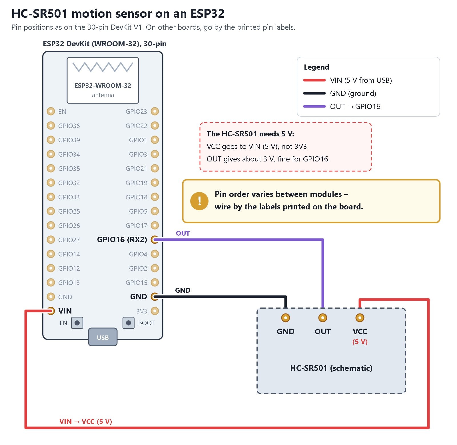
The order of VCC, OUT and GND differs from module to module, so wire by the labels printed on the board. On many 30-pin boards, GPIO16 is labeled “RX2”.
Project 2 already created the binary_sensor: section, and each section can appear only once per file. Add just this entry directly below the window contact, indented the same way (two spaces before the dash):
  - platform: gpio
    pin: GPIO16
    name: "Motion"
    device_class: motion
    filters:
      - delayed_off: 30s
Skipped Project 2? Then put binary_sensor: on its own line, with no indentation, right above this entry.
Install the update over Wi-Fi. delayed_off: 30s keeps the motion state on for 30 seconds after the last movement.
The module has two small potentiometers: one sets the sensitivity (how far away it picks up motion), the other the hold time, meaning how long the output stays on after it detects motion. To set them:
- Turn both pots all the way counterclockwise. That’s the shortest hold time, and
delayed_offtakes care of the rest. - If the sensor barely reacts, turn one of them to about the middle.
- If the motion state stays on much longer than 30 seconds after a brief movement, you turned the hold-time pot. Turn it back all the way and turn the other one to about the middle instead.
The complete config with all three sensors
With all three projects in place, the end of the file looks like this. If you needed inverted: true in Project 2, keep that line in your file:
i2c:
  sda: GPIO21
  scl: GPIO22
  scan: true

sensor:
  - platform: bme280_i2c
    temperature:
      name: "Temperature"
      oversampling: 16x
    pressure:
      name: "Pressure"
    humidity:
      name: "Humidity"
    address: 0x76
    update_interval: 60s

binary_sensor:
  - platform: gpio
    pin:
      number: GPIO4
      mode:
        input: true
        pullup: true
    name: "Window"
    device_class: window
    filters:
      - delayed_on: 10ms
      - delayed_off: 10ms
  - platform: gpio
    pin: GPIO16
    name: "Motion"
    device_class: motion
    filters:
      - delayed_off: 30s
The configs from this guide are in the esphome/en folder of our GitHub repository.
Automation: turn on a light when motion is detected
This Home Assistant automation turns on the light as soon as the sensor triggers:
triggers:
  - trigger: state
    entity_id: binary_sensor.living_room_motion
    to: "on"
actions:
  - action: light.turn_on
    target:
      entity_id: light.living_room_ceiling
To set it up, go to Settings → Automations & scenes, click Create automation and then Create new automation. Open the three-dot menu, choose Edit in YAML, replace the contents with the block above and click Save.
Replace light.living_room_ceiling with your own light’s entity ID. The motion sensor’s entity ID is built from the device name and the sensor name, here “Living room” and “Motion”, so it may differ on your system. You’ll find both entity IDs under Settings → Devices & services → Entities. To build automations in the UI without YAML, see our Home Assistant automations guide.
From breadboard to wall: a permanent setup
Off the breadboard
Over time, breadboard connections can work loose, and two breadboards take up a lot of room in an enclosure. For a permanent setup, solder the board and the sensor wires onto a piece of perfboard, ideally with the board in female headers so you can pull it out later. If you’d rather not solder, plug the sensors straight onto the board’s pins with female-to-female jumper wires. The reed switch’s thin stranded wires then go into a small screw terminal block, with a jumper wire on the other side.
Keep the BME280 away from the board’s heat
An ESP32 board runs warm: the processor and Wi-Fi never stop, and the voltage regulator gives off heat. If the BME280 sits right next to it or in the same tight enclosure, it reads too warm and too dry. Move the sensor 10 to 20 cm (4–8 in) away on a cable, ideally below the board and outside its enclosure. For much longer cable runs, ESPHome recommends external pull-up resistors on SDA and SCL (see the ESPHome I2C docs).
Power supply
According to the ESP32-WROOM-32E datasheet, the ESP32 draws around 240 mA while transmitting, with peaks up to about 380 mA. Espressif recommends a supply that can deliver at least 500 mA, so a 1 A power supply leaves plenty of headroom. Plan on one power supply per board. A supply with an attached USB-C cable means one less loose cable.
- Power bank: only models with an always-on or low-current mode work. Some power banks switch off after a while when the current draw is this low.
- PoE: if there’s a network cable where the sensor goes, a PoE splitter with a USB output can power the regular board, or you can use a PoE board (see Which ESP32 board should you buy?). Either way you need a PoE switch or injector.
Indoor enclosures
For wall mounting, a 3D-printed case with vents works well, with the sensor in its own compartment or on the outside, such as this ESP32/ESP8266 case on Thingiverse. PETG handles heat better than PLA, which can warp on a sunny windowsill. If you don’t have a 3D printer, use an IP65 junction box*, drill holes for the USB and sensor cables, and mount the BME280 outside the box.
Outdoor enclosures
Direct sunlight badly skews the readings. Put the sensor in a radiation shield: a white louvered housing that keeps out sun and rain but lets air through. There’s a printable one for the BME280 on Thingiverse; print it in white. The board stays dry in the IP65 box, with the BME280 on a short cable inside the shield. Don’t put the sensor in a sealed box, because moisture condenses inside and throws off the humidity readings.
Power the board over a USB cable, either from a power supply in an outdoor outlet whose flip cover still closes with the plug in, or from one indoors with the cable run outside. PoE is another option. For the temperature sensor alone, the battery version works too.
Running on battery: XIAO ESP32-C3 and deep sleep
On battery, an ESP32 DevKit won’t last long: its USB-to-serial chip and voltage regulator keep drawing current even while the ESP32 sleeps. For battery use, go with the Seeed XIAO ESP32-C3 with pre-soldered headers* instead. You’ll also need a 3.7 V LiPo battery of around 1000 mAh*, a BME280, and a soldering iron and solder to attach the battery.
To make the battery last, the XIAO spends most of its time in deep sleep: the chip shuts down almost everything, wakes up at a fixed interval, connects to Wi-Fi, sends its readings and goes back to sleep.
How long does the battery last?
Battery life depends almost entirely on how often the board wakes up. Seeed rates the XIAO ESP32-C3 at 75 mA with Wi-Fi active and 44 µA in deep sleep. For a 1000 mAh battery, that works out to:
| Cycle (awake / asleep) | Average current | Calculated runtime |
|---|---|---|
| 10 s / 50 s | about 12.5 mA | about 3 days |
| 10 s / 10 min | about 1.3 mA | about 1 month |
| 10 s / 30 min | about 0.5 mA | about 3 months |
For a room sensor, 10 minutes is plenty, because room temperature rarely changes faster than that.
What deep sleep means day to day
- Between readings, Home Assistant shows the last value.
- While asleep, the board can’t receive updates. The Device Builder queues the update and installs it as soon as the device wakes up. If that fails, install the update over USB.
- This setup doesn’t suit the window contact or the motion sensor: while asleep, the XIAO only notices an open window the next time it wakes up, and the motion sensor needs 5 V, which isn’t available on battery.
- To recharge, plug the XIAO into a USB power supply or your computer over USB-C. According to Seeed, the battery can stay connected while you do, because the board has a built-in protection circuit.
- To monitor the battery level, you need a voltage divider made of two resistors on an analog pin; the Seeed wiki shows how.
All deep sleep options are covered in the ESPHome deep sleep documentation.
Assembly
- Snap the included antenna onto the XIAO’s small U.FL antenna connector. Without it, Wi-Fi reception is weak.
- Solder the battery to the BAT+ and BAT− pads on the underside; there is no socket. If your battery has a plug, snip the two wires one at a time. Cutting both at once shorts the battery. Watch the polarity: red usually goes to BAT+ and black to BAT−, but check the markings on the battery.
- Connect the BME280 to the XIAO’s I2C pins.
BME280 → XIAO ESP32-C3
VCC    → 3V3
GND    → GND
SDA    → D4 (GPIO6)
SCL    → D5 (GPIO7)

Only on 6-pin modules:
CSB    → 3V3 (I2C mode)
SDO    → GND (address 0x76)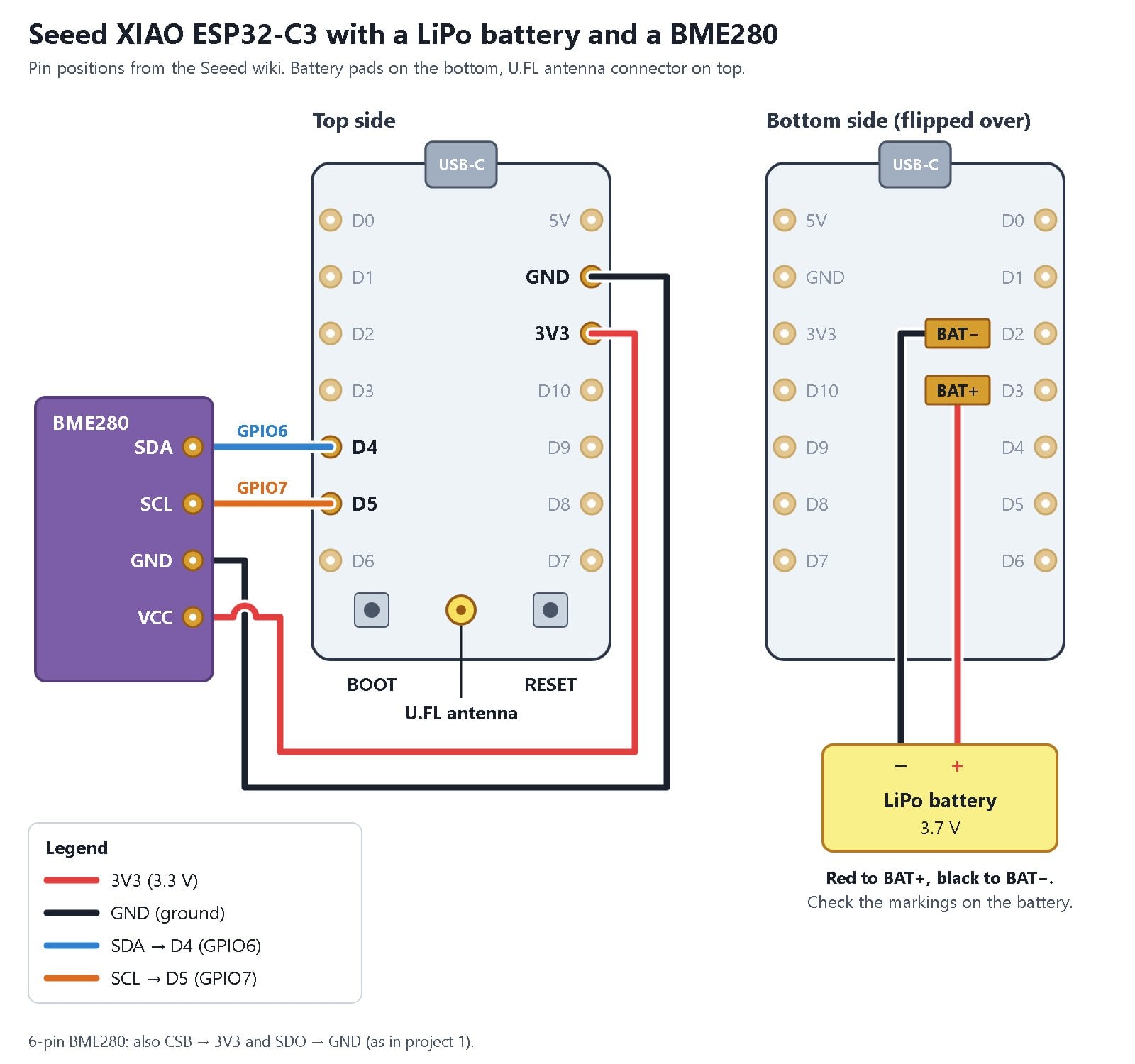
According to Seeed’s pinout, pins D4 and D5 are the XIAO’s I2C pins; in the config they’re GPIO6 and GPIO7. The i2c: block below sets them, so copy it as is. If you add I2C through the device navigator instead, the Device Builder fills in the pins from its board catalog, which for the XIAO are GPIO8 and GPIO9. Those are strapping pins that affect how the chip boots, and on the XIAO they’re routed to different pads. So if your file already has an i2c: block with GPIO8 and GPIO9, replace it with the one below.
Enclosures and mounting work the same way as for the USB-powered board (see Indoor enclosures and Outdoor enclosures).
Create and configure the device
If you haven’t created the device yet, follow Create your first device in the Device Builder. Choose “Seeed XIAO ESP32C3” under Select your board and give it its own name, such as “Bedroom”, then add encryption: under ota: in the editor. Then add this block to the end and click Save:
i2c:
  sda: GPIO6
  scl: GPIO7
  scan: true

sensor:
  - platform: bme280_i2c
    temperature:
      name: "Temperature"
      oversampling: 16x
    pressure:
      name: "Pressure"
    humidity:
      name: "Humidity"
    address: 0x76
    update_interval: 60s

deep_sleep:
  run_duration: 10s
  sleep_duration: 10min
With these settings, the chip wakes up every 10 minutes and goes back to sleep after 10 seconds. update_interval: 60s doesn’t get in the way: the BME280 takes its first reading within about five seconds of waking up, well inside the 10-second window.
Flash it and add it to Home Assistant
- Plug the XIAO into the Raspberry Pi with the data cable and click Install → Plug into your Home Assistant server, as described in Flash the board over USB and add it to Home Assistant. If no port shows up, hold the XIAO’s BOOT button while plugging in the cable.
- Once the XIAO is awake and on your Wi-Fi, it appears in Home Assistant under Settings → Devices & services in the “Discovered” section. Click Add.
- The XIAO only responds during its 10 seconds awake. If adding it fails, press its RESET button to wake it and try again right away.
Back up your configs
The configs live in Home Assistant’s /config/esphome/ folder, so they’re part of every regular Home Assistant backup and move with you to a new Pi. If you want to track changes, put the folder in a Git repository as well.
Troubleshooting
| Problem | Cause | Fix |
|---|---|---|
| BME280 shows no readings | wrong I2C address, a BMP280 instead of a BME280, or CSB not connected | look for the detected address in the log and set 0x76 or 0x77; on 6-pin modules tie CSB to 3V3; no humidity means it’s a BMP280 |
| Device shows “Offline” in the Device Builder | not flashed yet, the battery sensor is asleep, or the Device Builder can’t reach the board on the network | normal before the first flash, and for the battery sensor between wake-ups; otherwise check that the board is on Wi-Fi; if the Wi-Fi details are wrong, connect to the fallback hotspot and re-enter them |
| First flash fails or no port appears | charge-only cable, missing driver or board not in flash mode | use a data cable*, install the CP210x or CH34x driver, hold BOOT while plugging in; on a PC use Chrome, Edge or Firefox 151+ |
| Update over Wi-Fi fails | the board is asleep (deep sleep), or its firmware predates ESPHome 2026.9 | battery sensor: wait for it to wake up, or flash over USB. Only affects boards that were already running firmware from before ESPHome 2026.9. Old firmware can’t offer encryption. Once you’ve added encryption:, the Device Builder refuses to send an unencrypted update (“the device did not offer encryption; refusing to send the image in plaintext”). Flash over USB once, or follow the migration steps in the ESPHome docs. |
| Readings show “Unavailable” while the battery sensor sleeps | deep sleep added after setup, with Home Assistant older than 2025.5.2 | update Home Assistant; if that doesn’t help, delete the device under Settings → Devices & services and add it again |
| Motion sensor never triggers | HC-SR501 powered from 3.3 V | connect VCC to the board’s 5 V pin (VIN) |
| Window shows “Open” while it’s shut | the reed switch opens when the magnet is near | add inverted: true under pin: |
| Home Assistant doesn’t find the device | the network blocks automatic discovery (mDNS) | go to Settings → Devices & services → Add integration → ESPHome and enter the board’s IP address (find it in your router or in the Device Builder log) |
Where to go from here
For more sensors, browse ESPHome’s component list. Each page shows a YAML block that you add to the end of the file. If the file already has that section, such as sensor:, add just the entry below it, as with the motion sensor.
Frequently asked questions about ESPHome
ESPHome generates custom firmware for microcontrollers like the ESP32 from a short YAML description. The finished device reports its sensor readings to Home Assistant over Wi-Fi, with no cloud involved. ESPHome is an open-source project of the Open Home Foundation, which Home Assistant also belongs to.
Partly. The Pi runs the ESPHome Device Builder as an app in Home Assistant, where you create devices and compile their firmware. The firmware itself runs on the ESP32. A Raspberry Pi Pico 2 W, however, can be an ESPHome device itself.
Tasmota is a ready-made, general-purpose firmware that you flash and then set up in its web interface, usually sending data over MQTT. ESPHome builds firmware for each device from your YAML file. For DIY sensors with Home Assistant, ESPHome is the usual choice, because it talks to Home Assistant directly, without an MQTT broker.
No. The YAML file describes what the device should do, and since version 2026.6 you can also add components from a catalog in the Device Builder. You only need C++ for special cases, such as custom calculations in lambdas (short C++ snippets inside the YAML).
Yes. An ESPHome device can send its readings to other systems over MQTT, and the web_server component gives it its own web interface.
That depends almost entirely on how often it wakes up. With a XIAO ESP32-C3 and a 1000 mAh battery, the math says a few days if the sensor reports every minute and several weeks at a 10-minute interval. In practice, expect less.
Related guides
- Install Home Assistant on Raspberry Pi
- Home Assistant: Raspberry Pi 5 or N100 mini PC?
- Raspberry Pi vs. Arduino vs. ESP32
- Raspberry Pi Pico 2 W with ESPHome
- Set up the ESP32-C6 as a Zigbee router
- Zigbee sensors for Home Assistant
- Home Assistant automations guide
- MQTT on the Raspberry Pi
- Raspberry Pi sensors at a glance